The Symbols - hydraulics and pneumatics command contains elements that are used in creation of hydraulics and pneumatics schemes.
Creating installation schemes is associated with drawing lines, inserting symbols and describing drawings. CADprofi program gives to the designer, the appropriate commands, that make it easier to describe scheme elements, thanks to which it is possible to create BOMs from the symbols and lines that are used in projects.
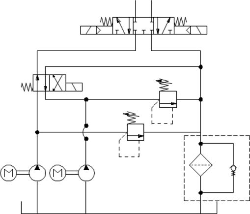
An exemplary scheme
All symbols available in CADprofi program are being inserted as blocks, which can be copied, deleted or edited with the use of standard CAD program commands. Most symbols can be also edited with the use of CADprofi editing commands such as: Quick edit, Edit symbols and Delete symbols.
Symbols are often used to graphically represent real devices, armature and other installations elements, therefore it is possible to add technical parameters, about the products used in the project, to the symbols (Attributes and descriptions command), as well as numbering and symbols' marks. This information can be used when describing drawings when creating graphical legends or specifications.
Program possesses several options that make it easier to insert symbols in the drawing.
|
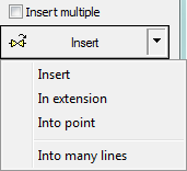
Main options (available after pressing the
•Insert symbol. •Into many lines. •In extension. •Into point. |
|
‘Insert symbol’ option
This is the default option that allows to insert symbols in any point or into a line indicated by user. When inserting symbols into lines, the symbol insertion angle depends on the line angle (the angle specified in the dialog box is being ignored).
6 Procedures
1. Select the symbols from any library.
2. Click the Insert symbol button. The library dialog window will close allowing insertion of symbol into the drawing.
3. Point into a line, in which you would like to insert the symbol.
4. (Optional) Click anywhere in the drawing to insert a symbol.
5. (Optional) Specify the rotation angle of inserted symbol - this option is available only if user has selected the Rotate option in the library dialog window.
|
| |
|
Insert into a line |
Insert in any point |
‘Into point’ option
The Into point option may be used when it is necessary to insert the symbol in a point that lies on a line, but in such a way that the symbol won't "adjust itself to the line". In this option, the inserted symbol "ignores" the line, so it does not break it and it does not take angle from it. This option is used in many situations for example when inserting sensors, which usually need to touch lines.
6 Procedures
1. Select the symbols from any library.
2.
With the use of  button,
pull-down the insertion list.
button,
pull-down the insertion list.
3. Click the Into point button and insert the symbol into the drawing.
4. Point into a point in a line, in which you would like to insert the symbol.
5. (Optional) Click anywhere in the drawing to insert a symbol.
6. (Optional) Specify the rotation angle of inserted symbol - this option is available only if user has selected the Rotate option in the library dialog window.

Inserting a symbol without adjusting it into the line
‘In extension’ option
The In extension option allows to precisely specify the symbol insertion point in relation to other objects located in the drawing. This allows to insert a symbol in a point in accordance with for example another symbol.
6 Procedures
1. Select the symbols from any library.
2.
With the use of button,
pull-down the insertion list.
3. Click the In extension button. The library dialog window will close allowing insertion of symbol into the drawing.
4. Click a line, in which you would like to insert the symbol (P1).
5. Specify the symbol insertion point against you would like to specify the location of the inserted element (P2).
6. Specify an additional offset or click Enter to confirm the insertion point.
7. (Optional) Specify the rotation angle of inserted symbol - this option is available only if user has selected the Rotate option in the library dialog window.
8. Symbol will be inserted in the drawing and the command will end (if user has not selected the Insert multiple option).
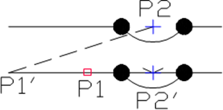
Inserting in extension
‘Into many lines’ option
Into many lines option gives the possibility to quickly insert selected symbol into many lines.
It allows to insert selected symbol into all lines that cross with the „indication line”, that was specified during insertion (P1-P2).

Inserting symbols into many lines
6 Procedures
1. Select the symbols from any library.
2.
With the use of button,
pull-down the insertion list.
3. Click the Into many lines button. The library dialog window will close allowing insertion of symbols into the drawing.
4. Specify the first point of the “crossing line” that will cross with lines (P1).
5. Specify the second point of the “crossing line” that will cross with lines (P2).
6. The selected symbol will be inserted in all lines that crossed with the “crossing line”.
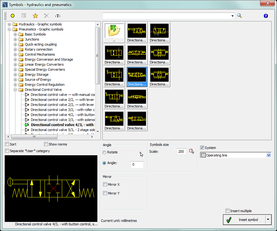
Symbols - hydraulics and pneumatics dialog window
The Symbols - hydraulics and pneumatics dialog window contains the following elements:
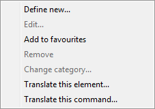
Tools menu:
 Define
new - allows to add a new element to the database. Read more about
it in the Defining user
blocks.
Define
new - allows to add a new element to the database. Read more about
it in the Defining user
blocks.
 Edit - allows to Editing user block parameters.
 Add to
favourites - copies symbol to the *Favourites*.
Add to
favourites - copies symbol to the *Favourites*.
 Delete - deletes the selected symbols from the *Favourites* category.
|
Pop-up menu - options menu for the selected symbol, which is available after right clicking on the mouse button on the selected symbol. Commands in this menu are similar to the tools menu. |
|
Category tree - a set of all categories and symbols in the library, shown as a pull-down tree. User can customize the display order by using the following options:
•Sort - alphabetical order of categories placement and their content.
•Norms- enables/disables displaying symbols according to norms.
Thumbnail view - displays the content of currently selected category as thumbnails.
Preview - displays the preview of the currently selected symbol. Right-clicking on the preview window will zoom the view.
Angle/Rotation - possibility to specify a fixed angle when inserting an element or enabling the rotation option, in which element’s angle is defined by rotation during insertion.
Scale - specifies the size of inserted symbols. It is possible to enter the scale value or to indicate a symbol on the drawing whose scale user would like to use.
System - if in the program options, the extended layer name structure is enabled then symbols will be inserted on layers depending on the kind of installation (system). In case of inserting symbols into an existing line then the System option is being ignored and the symbol layers depends on the line kind.
Mirror X, Y- enabling this option will create an X or Y mirror image for the specified object.
Insert multiple- enables/disables the possibility of inserting multiple symbols to the drawing. The insertion process requires from the user to press the Enter or Esc key when he finished inserting multiple symbols.
6 Procedures
Always encrypt files in transit and at rest.
As we navigate the complexities of the digital world, it's essential to remain vigilant and aware of potential risks associated with unique file identifiers and digital asset management systems. By doing so, we can ensure a safer and more secure online environment for everyone.
, a standard that provides a resolution of 1920x1080 pixels. Compared to the grainy, standard-definition formats of the late 20th century, FHD represents a leap in clarity that allows for the preservation of fine details. When we archive video today, we are no longer just capturing a sequence of events; we are capturing textures, expressions, and environmental nuances that were previously lost to technical limitations. This level of detail ensures that future generations can view historical footage with a sense of "being there," bridging the temporal gap between the past and the present. The Power of the MP4 Container The use of the fhdarchivejuq722mp4
This specifies the video resolution. FHD universally denotes a resolution of 1920x1080 pixels, featuring a 16:9 aspect ratio. This tells the system or user exactly what quality tier the file belongs to before it is ever opened.
If you are currently setting up a media server or organizing a digital collection, I can help you optimize your file structure. Would you like me to into a standardized format, or would you prefer a guide on configuring metadata tags for media assets? Share public link Always encrypt files in transit and at rest
: Strings of this nature frequently appear in search trends due to automated scripts, web scrapers, or specific database leaks where internal file lists temporarily become indexed by public search engines. How to Find What You Are Looking For
The standardized container format. The MPEG-4 Part 14 format is highly favored in digital archiving because it balances high-quality H.264 or H.265 video compression with universal device compatibility. The Role of Naming Conventions in Digital Archiving , a standard that provides a resolution of 1920x1080 pixels
Always generate a (such as an .md5 or .sha256 file) alongside the video. Periodically running a validation check ensures the underlying bits of the video container remain uncorrupted over years of storage. Furthermore, keeping an off-site backup—using the classic 3-2-1 backup strategy—guarantees that a localized hardware failure will not erase your high-definition media collection.
If you can tell me (e.g., a specific website, a document, a file transfer log), I may be able to provide more specific context on what it represents.

 Creating
pneumatic
schemes
Creating
pneumatic
schemes